In Vitro Head-to-Head Comparison of Flow Reduction between Fibered and Non-Fibered Pushable Coils
Article information

Abstract
Purpose
To compare the embolization effects of a non-fibered pushable coil with a conventional fibered pushable coil in an in vitro bench-top experiment.
Materials and Methods
A simplified vascular phantom with 4 channels (1 for the non-fibered coil, 1 for the fibered coil, and 2 for continuous circuit flow) was used. A single coil of the longest length was inserted to evaluate the effect of single-coil embolization, and 3 consecutive coils were inserted to assess the effect of multiple-coil embolization. Post-embolization angiography was performed to obtain flow variables (time to peak [TTP], relative peak intensity [rPI], and angiographic flow reduction score [AFRS]) from time density curves. The packing densities of the two coil types were calculated, and the AFRS of each channel was determined by dividing the TTP by the rPI.
Results
When inserting a single coil, the conventional fibered coil demonstrated better flow reduction, as indicated by a higher AFRS (25.6 vs. 17.4, P=0.034). However, the non-fibered coil exhibited a significantly higher packing density (12.9 vs. 2.4, P=0.001). Similar trends were observed with multiple coils.
Conclusion
The conventional fibered pushable coil showed better flow reduction efficiency, while the non-fibered pushable coil had a higher packing density, likely due to the flexibility of the coil loops. A better understanding of the distinct characteristics of different pushable coils can enhance the outcomes of various vascular embolization.
INTRODUCTION
Ever since Gianturco et al. [1] first introduced prototype embolization coils in 1975, these coils have been widely utilized as a primary tool in various endovascular procedures. After removing tungsten coils from the angio room shelves due to long-term safety concerns associated with the metal material, the majority of coils are now made of platinum [2-4]. Although detachable coil technology has become popular in our neurointerventional field, conventional pushable coils still play a role in various vascular embolization procedures [5-8]. In neurovascular procedures, such as venous sinus procedures, various arteriovenous fistulae, trapping of an artery, and other embolization procedures, pushable coils are still preferred not only due to their cost-effectiveness but also because they offer a higher packing density compared to thinner coils [3,9,10]. In this sense, it is meaningful to understand the basic characteristics of conventional embolization coils, especially for beginners.
When the house-made prototype embolization coil (i.e., “wool coil”) was first introduced by Gianturco et al. [1], the metal part of the short coil was not the main component of the embolization device. Instead, they aimed to take advantage of the thrombogenic properties of fibers, such as cotton and wool. The coil was used to deliver and securely place these fibers in the target vessel [1]. Since then, both metal coils and fibers have become the two main components of pushable vascular coils introduced afterwards, such as Hilal coils (COOK Medical), Tornado coils (COOK Medical), Vortex coils (Boston Scientific), and Nester coils (COOK Medical) [11,12]. While fibered versions of detachable coils (Interlock, Boston Scientific; Concerto coil, Medtronic) are available, there are currently no non-fibered versions of pushable metal coils available in the market, at least in Korea [13].
Since most detachable coils are non-fibered, it has become common to assume that most types of pushable coils are fibered [14]. Non-fibered pushable coils can also be used in procedures that do not require a detachable mechanism, such as trapping a vessel segment or performing transvenous coil embolization of dural arteriovenous fistulas [15]. Recently, a new non-fibered pushable microcoil (HansBiomed) was introduced. This coil is deliverable through standard smallbore (inner diameter of 0.0165 or 0.017-inch) neurovascular microcatheters. In an initial bench-top test, the new coil system appeared to be softer and easier to deploy than conventional pushable coils. The purpose of this in vitro bench-top experiment was to compare the new non-fibered pushable coil system with the conventional fibered pushable coil system (K3; Taewoong Medical), focusing on evaluating the flow reduction and packing density of the coil mass in the target vessel.
MATERIALS AND METHODS
Embolization Coils
Two types of pushable coils were prepared, including anchoring coils in both fibered and non-fibered forms (Table 1). The fibered pushable coil used in this study was the K3 coil, which is a platinum-based embolization coil mixed with nylon fibers. The non-fibered pushable coil was made by HansBiomed, a simple platinum-based embolization coil similar to the coil part of detachable coil systems used for cerebral aneurysm embolization (Fig. 1).
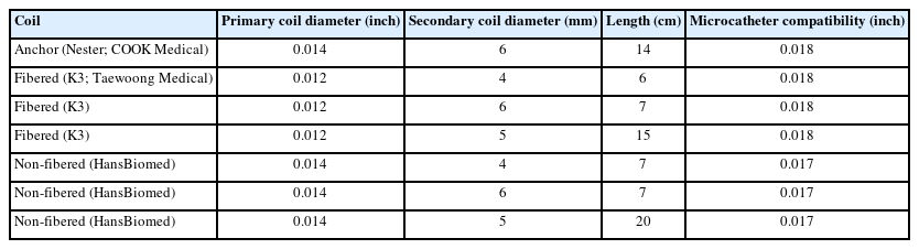
Wire diameter, diameter length, and microcatheter compatibility of the pushable coils of interest

Photographs of the (A) non-fibered and (B) fibered embolization coils used in this study.
The Vascular Model and Closed Flow Circuit
The simplified silicone vascular model (Fig. 2A) had an inner diameter of 5 mm and featured 4 parallel channels. Two inner channels were designated for coil embolization, while the 2 outer channels maintained flow when the middle channels were occluded with coils (Fig. 3A). To ensure stable anchoring of the first coil, a short, tapered portion was intentionally created in the middle of the parallel channels, resulting in a 4 mm inner diameter for the distal segment of all 4 channels.
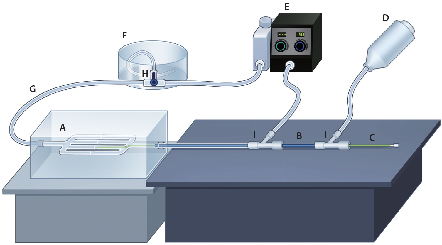
Illustration of a flow and a contrast injection system. (A) Vascular phantom, (B) guiding catheter, (C) microcatheter, (D) automated power injector, (E) pulsatile pump, (F) large-volume drain container, (G) silastic tube, (H) stopcock, (I) hemostatic valve.
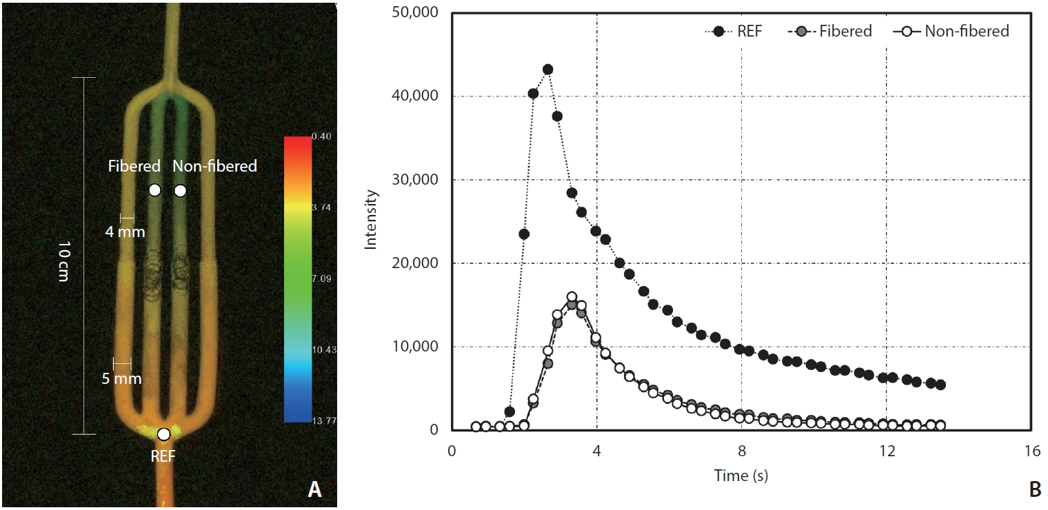
Vascular phantom model post-processed with iFlow (A) and time density curve obtained with iFlow (B). REF, reference.
This vascular model was connected to a closed circuit made of a silastic tube (HSW) with a 5 mm inner diameter (Fig. 2G). The circuit was completed by connecting it to a large-volume drain container (Fig. 2F) and a pulsatile pump (FlowTek 125; United Biologics) (Fig. 2E). The flow was maintained with saline by adjusting the continuous, pulsatile flow to 50% of the maximum flow. A hemostatic valve (Ace airvent RHV; Hubiomed) (Fig. 2I) was added, allowing for the insertion of a 5-Fr guiding catheter (Grafia; Sungjin Hitech) (Fig. 2B) with its tip placed 6 cm proximal to the branching site of the vascular model. Contrast injection was performed through the guiding catheter.
Angiographic Image Acquisition
Digital subtraction angiography (DSA) images were obtained using the frontal C-arm of a biplane angiographic machine (Artis Zee; Siemens). The position of the phantom remained fixed at a 100 cm focal spot-to-detector distance (Fig. 2). Image acquisition conditions included no C-arm angulation, no collimation, and a 32-cm field of view using the small focal spot. DSA images were acquired before and after completing a set of coil insertions in both channels. The images were captured at a rate of 7.5 frames per second for a duration of 20 seconds [16].
Iopamidol 300 mgI/mL (Pamiray; Dongkook Lifescience) was used as the contrast agent and injected using an automated power injector (Medrad Mark V ProVis; Bayer) (Fig. 2D) with a pressure limit set at 300 psi. The injection was performed for 1 second at a fixed rate of 3 mL/s. Before each contrast media injection, the direction of the circuit drain was changed towards the drainage container using the stopcock (Fig. 2H).
Coil Embolization
An experienced interventionist performed the embolization procedures after setting up the closed circuit on the table. A microcatheter was inserted after positioning the tip of the catheter. The microcatheter used for delivering K3 coils and Nester coils was a 0.021-inch microcatheter (Prowler Plus; Cerenovus), and a 0.017-inch microcatheter (Headway 17; MicroVention) was used for non-fibered coils (Fig. 2C). All coils were delivered using a pusher wire (Synchro 14; Stryker Neurovascular).
Since the non-fibered coils could not be stably placed as the first anchoring coil, an oversized sturdy coil (Nester coil, 6 mm×14 cm) was used as the anchoring coil for both inner channels. All channels had a tapered section in the middle, which facilitated the convenient and secure positioning of the anchoring coil. Two different coil embolization techniques were used: one to assess the flow reduction capacity of a single coil and the other for multiple coils.
In order to compare the embolization effect of a single coil, the longest coil of each type with a diameter of 5 mm was selected. One channel was treated with a fibered K3 coil (5 mm by 15 cm), and the other channel was treated with a non-fibered coil (5 mm by 20 cm). The operator was asked to pack the coil as tightly as possible. This process was repeated 10 times, with the sides of the channels for each coil selected alternatively.
To compare the effect of multiple-coil embolization, 3 coils, excluding the anchoring coil, were consecutively inserted for both channels. One channel was packed with 3 fibered K3 coils in the order of 6 mm by 7 cm, 4 mm by 6 cm, and 4 mm by 6 cm, while the other channel was packed with 3 non-fibered coils in the order of 6 mm by 7 cm, 4 mm by 7 cm, and 4 mm by 7 cm. The experiment was repeated 3 times. The left-hand channel was fixed for K3 coils, while the right-hand channel was fixed for non-fibered coils in this multiple-coil experiment. DSA images were obtained before the delivery of the anchoring coil and immediately after the delivery of the final coil.
Image Analysis and Statistics
All images were transferred to the Leonardo workstation (Siemens Healthineers) for time-density curve analysis using Syngo iFlow (Fig. 3). We designated 3 regions by placing a circular region of interest (ROI) with an area of 13.90 mm2 at the region just before the branching site of the vascular model and distal to the coil mass of each embolized channel (Fig. 3). As a result, the peak intensity (PI) and time to peak (TTP) of those 3 ROIs were obtained. By designating the 1st ROI located proximal to the branching region as the reference, we calculated the relative PIs (rPIs) of both coiled channels by dividing their PIs by the reference PI.
We obtained the rPIs and TTPs of both coiled channels. To better visualize the distinction, a calculated parameter known as the angiographic flow reduction score (AFRS) was utilized; this score was obtained by dividing the TTP by the rPI, as the TTP tends to be prolonged and the rPI reduced when there is a decrease in flow. A higher AFRS was considered to indicate a better flow reduction.
Packing density was calculated as the ratio between the volume of the inserted coils (including the anchoring coil) and the volume of the vessel segment filled with the coils. The volume of the inserted coils was calculated using the formula for the volume of a cylinder, assuming the coil to be a thin and infinitely long cylinder (Volume=π×radius2×length). For the calculation of the vessel volume, we measured the length of the coil-filled segment using two-dimensional angiography [7].
Statistical analyses were conducted using the Wilcoxon signed-rank test. A two-sided P-value of 0.05 was used in this study. R Statistical Software, version 4.3.1 (R Foundation for Statistical Computing) was used for analyses. Since the repetition time for the experimental coil embolization, which was used to compare the effect of multiple-coil embolization, was only 3, no statistical analysis could be performed. The differences in the aforementioned flow parameters, including packing density, were presented using graphs to illustrate the trends.
RESULTS
The results of the comparison of the single-coil embolization effect are summarized in Table 2. The fibered coil showed a significantly higher AFRS compared to the non-fibered coil (25.2 vs. 17.4, P=0.034), mainly due to the significantly prolonged median TTP (4.8 seconds vs. 4.1 seconds, P=0.011). However, there was no significant difference in rPIs between the two coil types (21.0% vs. 24.5%, P=0.148). On the contrary, the packing density was significantly higher in the non-fibered coil (9.4% vs. 12.9%, P=0.001).

Results of single coil embolization
The results of the comparison of the multiple-coil embolization effect are summarized in Fig. 4. Similar trends in flow reduction and changes in packing density were observed when using multiple coils, with more pronounced differences as the number of embolized coils increased.
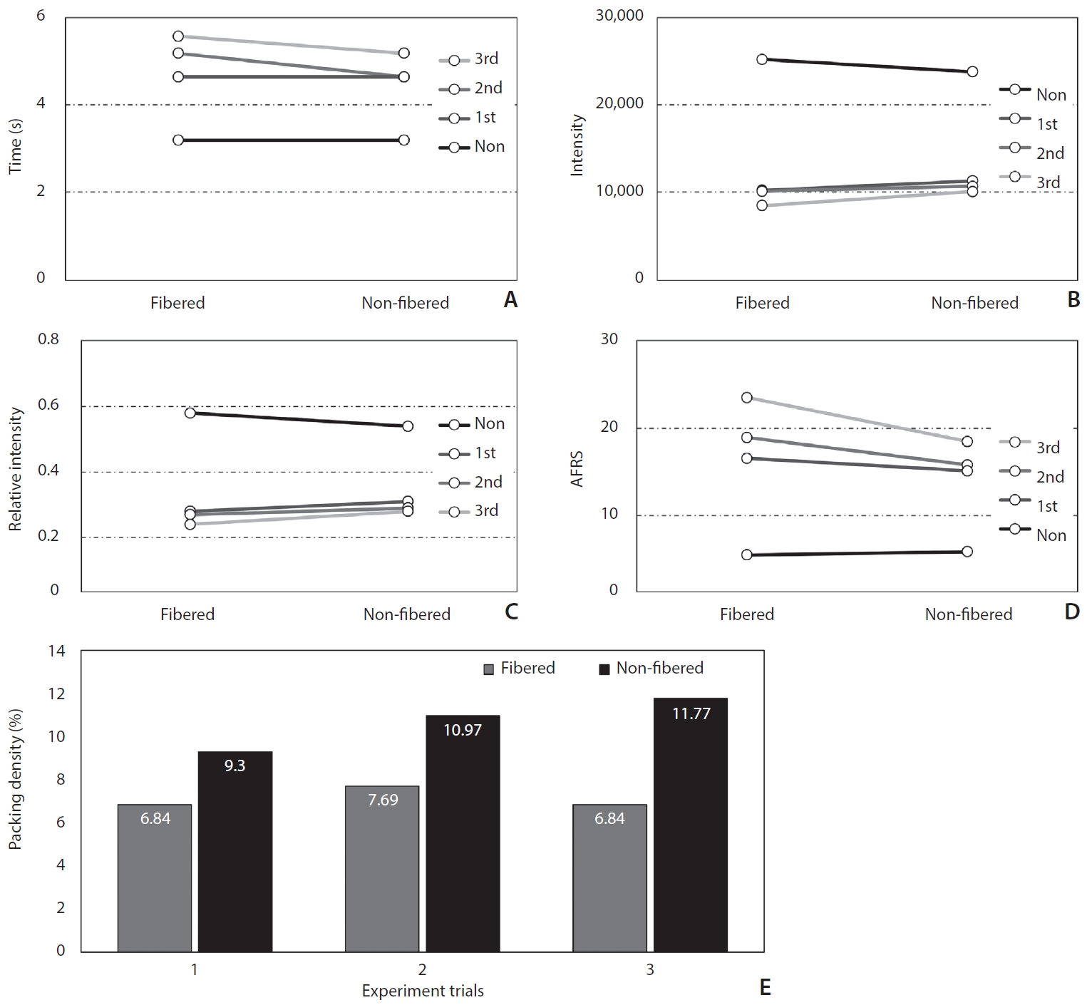
Results of multiple coil embolization. (A) Time to peak, (B) maximum intensity, (C) relative intensity, (D) angiographic flow reduction score (AFRS), (E) packing density.
DISCUSSION
Through time-density curve analyses on a simplified vascular phantom, we observed that the conventional fibered pushable coils had better flow reduction efficiency compared to the new non-fibered pushable ones, while the packing density was higher with the non-fibered coils [17]. In the historical review of the evolution of vascular coils, we found that the pioneers seemed to pay more attention to the fiber component rather than the metallic coil itself. Since then, most pushable coils have been manufactured as fibered versions. As observed in clinical practice with these fibered coils, the presence of fibers significantly improved flow reduction and reduced the number of coils needed for complete occlusion in multiple animal experiments [18-20].
However, the fibered versions were found to be stiffer and had a higher profile compared to their non-fibered counterparts despite their significantly better performance in flow reduction [21]. Fibered pushable coils are preferable for general embolization purposes. However, non-fibered coils can also be utilized to address the inherent limitations of fibered coils, as non-fibered coils are less rigid and can be packed more tightly [22], allowing for compensation of these limitations.
Considering the fibered pushable coil as the standard in vascular embolization [23-25], non-fibered coils may have additional roles in specific situations. Firstly, there are no fibered pushable coils available that are compatible with lower-profile microcatheters (inner diameter <0.017 inches) for neurovascular use. In this case, the lower profile of non-fibered coils could be advantageous when selecting coils for embolization of target lesions located far distally or lesions with small-sized vessels. Non-fibered coils, for example, can be used in the preoperative devascularization of hypervascular spinal bony tumors to protect non-target intercostal or segmental arteries. Since non-fibered coils can be delivered using lower-profile microcatheters, there is no need to use 2 separate microcatheters for particle and coil embolizations. Secondly, if both fibered and non-fibered pushable coils are available, their combined use could reduce the length of the coil-packing segment, as non-fibered coils can help fill the remaining spaces between the stiffer fibered coils. This could be very useful, especially when the target vascular structure has a narrow safety margin. This approach might help eliminate the need for more expensive detachable coils.
There are several limitations to this experiment. Firstly, the study was conducted using a simplified flow model filled with saline, which makes it impossible to accurately reflect the actual in vivo situation, which would involve successive thrombosis after coil packing. This is why we could not observe a complete cessation of contrast flow in any of the coil-packed channels. Secondly, as the embolization was performed by a single operator, it was not possible to determine if there were any differences based on the operator’s technique. Thirdly, there might be some debate as to whether iFlow is an appropriate tool for analyzing flow dynamics [17]. However, we believe that there would be no significant issues in comparing the efficiency of flow reduction by multiplying the rPI and TTP (AFRS). Lastly, when comparing the embolization effect of single coils, it would have been preferable to compare coils of the same length; however, we used a 15-cm fibered coil and a 20-cm non-fibered coil because they were the longest coils available for each type. The elevated packing density observed with the 20-cm non-fibered coil, notwithstanding its 5-cm increase in length, is inferred to be due to the negligible statistical difference in the volume of the vessel segment occupied by the coils (232.3 mm3 vs. 239.6 mm3, P>0.999). This outcome implies that non-fibered coils are capable of achieving more compact embolization within vessels as compared to the fibered coil, suggesting a potential advantage in the density of vessel occlusion.
CONCLUSION
We compared two types of pushable coils—fibered and non-fibered—used in vascular embolization procedures using a simplified flow model. The fibered coil demonstrated better flow reduction efficiency due to its higher packing volume, while the non-fibered coil exhibited a higher packing density because of the flexibility of its coil loops. Gaining a better understanding of these distinct characteristics of pushable coils will help improve vascular embolization outcomes.
Notes
Fund
This study was funded by HansBiomed (grant number 2021OM0558).
Ethics Statement
Institutional Review Board (IRB no.2021-1537) was exempted from review by IRB of Asan Medical Center since it did not involve human subjects; it was a paper applying devices to in vitro phantons.
Conflicts of Interest
YS and DHL have been editors of Neurointervention since 2018 and 2023, respectively. However, they have not been involved in the peer reviewer selection, evaluation, or decision process of this article. No potential conflict of interest relevant to this article was reported. No other authors have any conflicts of interest to disclose.
Author Contributions
Concept and design: DHL. Analysis and interpretation: JTY, BK, JHC, SMH, MK, SH, and YS. Data collection: JTY, BK, JHC, SMH, MK, SH, and YS. Writing the article: JTY and BK. Critical revision of the article: JTY, BK, MK, SH, and YS. Final approval of the article: BK, JHC, SMH, YS, and DHL. Statistical analysis: JTY and BK. Obtained funding: DHL. Overall responsibility: DHL.